You may be interested in…
-
Sale!
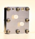
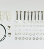
Build your own 5 cm2
Original price was: $2,702.00 – $3,092.00Price range: $2,702.00 through $3,092.00. Price range: $2,668.00 through $3,058.00Current price is: $2,668.00 – $3,058.00Price range: $2,668.00 through $3,058.00. Add to Cart
Electrolyzer Hardware -
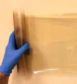
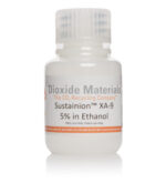
Sustainion® Alkaline Anion Exchange Membrane X37-50 grade T
Price range: $46.00 through $934.00 Select options This product has multiple variants. The options may be chosen on the product page